Frequently asked questions for FluidDraw P6 and P7
General
What are the system requirements for FluidDraw P6/P7?
FluidDraw P6/P7 runs on Windows 8 or higher with .Net Framework 4.8 installed including Windows 11 (both 32-bit and 64-bit). We recommend a dual core processor and at least 2 GB of RAM for 32-bit machines and 4 GB RAM for 64-bit PCs, respectively.
To topCan FluidDraw P6/P7 automatically search for updates?
Within the program options of FluidDraw P6/P7 you can select to search for updates and if you whish to automatically download them on each start of the program.
To topCan FluidDraw P6/P7 be installed to a network drive?
Yeah, that’s possible. Proceed as follows:
- First, perform the server installation. To do this, start the FluidDraw installation and select “Full installation (local or network)” as the installation type during the installation. Then choose the network drive for which the client PCs have read access as the destination folder.
A client installation will then be performed on each additional PC. Start the FluidDraw installation and select “Network (Client installation)” as the installation type this time. Only the CodeMeter drivers and a link to the installation on the network drive are then installed on the respective PC.
Note: During the client installation, no files other than the CodeMeter drivers are copied to the local hard disk and only a shortcut to the network drive is created. In particular, this means that only the server installation has to be updated for subsequent program updates; intervention on the individual workstation PCs is no longer necessary afterwards.
A client installation is licensed in the same way as a complete FluidDraw installation. Either a license of your license ticket is installed locally on the workstation PC or the licenses are available via a license server in the network.
To topWhy can't I access my network drives from FluidDraw P6/P7?
This is related to the User Account Control (UAC) settings. If FluidDraw is run directly after the installation or an update with elevated rights, the application will run under a different user account than the one under which the network drives are available.
If you restart FluidDraw without elevated rights, you can access your network drives again. Alternatively, you can make an entry in the registry that makes the network drives of your user available under elevated rights. You will find instructions including further background information with an Internet search for the term “EnableLinkedConnections”.
To topShopping carts from the new Festo online store do not appear in the selection in FluidDraw. How can I still transfer the shopping carts to FluidDraw?
In autumn of 2020 Festo SE launched a new modernized web presence. Migration of all old functionalities and interfaces into this new internet presence is not finished completely up to now. This also effects the external access to the online shopping baskets. For this reason, only your saved shopping carts from the old online store will be displayed in FluidDraw via the menu item Insert => From Festo Shopping Basket.
You can transfer a shopping cart from the new online store to FluidDraw using the following method:
- Call up the desired shopping cart in the Festo online store.
- Click the Export button at the top right of the cart.
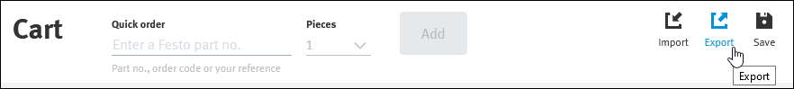
- Select Festo or FluidDraw format as export format. Then click Download to save the shopping cart as a CSV file on your PC.
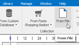
- You can now import the downloaded shopping cart into FluidDraw by selecting the From File command from the Insert menu.
Licensing
What type of licenses are available for FluidDraw P6/P7?
FluidDraw P6/P7 licenses are issued and managed via a ticket system. The ticket number is provided after the purchase. The licenses can be imported (activated) and managed via Internet.
The licenses can be imported into a license server and shared over the network, as well as used locally on a PC or notebook. A physical USB hardware key, such as the CodeMeter stick used for version P5, is not required. However, it is also possible to import licenses into an existing CodeMeter stick. Your licenses are managed with the Online Licenses Activation Wizard (short Activation Wizard), which is installed together with FluidDraw.
To topWhere can I find the activation wizard?
The activation wizard is included in the installation of FluidDraw P6/P7. You can access the wizard at any time via the Manage Licenses menu item on the Manage page. If FluidDraw could not be started due to lack of a valid license, you can access the activation wizard via the button Activate license… of the dialog box that appears.
Alternatively, the executable file CodemeterActivationWizard.exe can be found in the program directory of FluidDraw P6/P7 in the subdirectory /bin. This is a stand-alone version of the Activation Wizard and can also be used on PCs without FluidDraw installed.
The Activation Wizard runs under Windows 8 or higher with the .Net Framework 4.8 installed. For successful license management, the following requirements must also be met:
- The Activation Wizard must be able to connect to the Internet. Proxy servers with credentials are supported.
- The CodeMeter Runtime must be installed.
- If the licenses are to be installed on a remote PC, the CodeMeter Runtime must also be installed there and the PC must be accessible via the network.
I have received a ticket number. How can I activate my license(s)?
The ticket number you received from the licensor after purchasing represents your digital licenses for FluidDraw. You can now either import these digital licenses into a license server or locally onto your PC. A direct Internet connection is required.
Activation of a license on a single PC:
The main steps are briefly described below. A detailed description including screenshots can be found in the first chapter of the FluidDraw manual.
- If not already done, download the installation program for FluidDraw here from our download area.
- Install and start FluidDraw on the desired PC.
- FluidDraw searches for available license servers in the network at startup. If no license was found, a dialog appears with a corresponding message. In this dialog, click on
"Activate license...to start the activation wizard. - You can now enter your ticket number in the activation wizard. Follow the steps through the wizard to activate the license on your PC.
Setting up and importing the licenses to a license server:
In order for a computer in the network to become a license server, the following steps must be performed. For further details and screenshots, please refer to the first chapter of the FluidDraw manual.
- Install the CodeMeter Runtime. You have the following alternatives:
- Run the FluidDraw installation program and select the option to install a license server.
- Download the CodeMeter Runtime from the website of Wibu AG here and install it on the server.
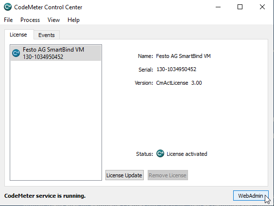
- Open the WebAdmin interface of CodeMeter. Start the CodeMeter Control Center and click on the WebAdmin button.
- Navigate via the menu Settings and Server to the item Server access.
- In the Network Server group, enable the Activate option.
Importing the licenses to the license server:
- Open the activation wizard and enter your ticket number.
-
In the further steps of the wizard, you can specify the license server as the target for the licenses to be activated.
Note: The import of licenses to the license server can be done via the network. However, we recommend that you run the activation wizard directly on the license server and install the licenses locally there.
License server note:
The licenses installed on the license server are bound to this server. If the characteristics of the server are changed, the licenses may become invalid. Before you make any changes to the server, we recommend that you first deactivate the existing licenses and then reactivate them after the changes have been made.
Can licenses for FluidDraw P6/P7 also be imported into an (existing) CodeMeter USB connector?
Yes, that is possible. The activation wizard for activating FluidDraw licenses via a ticket number also supports the import of licenses into an existing CodeMeter USB stick.
To topHow can a local license be transferred to a new PC?
For this, you need your ticket number, which you received after purchasing FluidDraw.
Call up the activation wizard on the outgoing PC and enter your ticket number. You can now use the wizard to deactivate the local license and this license will be released again on the license server. You can then activate FluidDraw P6/P7 as usual on the new PC with the ticket number.
To topLicense renewal
When are FluidDraw 365 subscription licenses renewed?
Unless the FluidDraw 365 subscription is cancelled, the licence on Festo’s servers is extended by one year on the day the contract was concluded. If, for example, the contract was concluded on May 03, 2019 the contract will be renewed on May 03 of the respective following year. The subscription license is valid for one year plus a grace period of seven days. After the subscription contract has been renewed, the license renewal must be processed within these seven days, otherwise FluidDraw will no longer start. However, it is still possible to perform a license renewal afterwards.
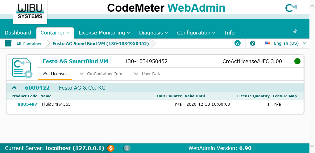
To topHow can I check the expiry date of a license?
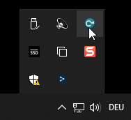
Open the CodeMeter Control Center by clicking on the respective icon in the info area of the task bar.
Launch the WebAdmin by pressing the corresponding button at the bottom right of the control center.
If the licenses are installed on a license server in the network, you must first select the corresponding license server in the lower area of the WebAdmin.

The licenses are listed in the “Container” tab. In the following example the FluidDraw subscription runs until Dec. 23, 2020. On this day the license is automatically renewed on the Festo servers. The locally installed license, that you can see in the screenshot, is valid until Dec. 30, 2020 because it includes the seven day grace period. Within these seven days the local license should be renewed. An internet connection is needed therefore.
How do I renew a license?
For the license renewal FluidDraw version 6.0k from 11/25/2019 or newer is needed. An update can be initiated directly from FluidDraw via the main menu item “Help” => “Check for Updates” if an Internet connection is available. Alternatively you can download the update from our Download page for FluidDraw P6.
Starting with version 6.0k, the license is automatically updated when FluidDraw is started, as long as the subscription is still valid and FluidDraw has an Internet connection. Without an Internet connection or if automatic renewal is not possible, the license can be updated manually using your ticket. For this you need the program Codemeter Activation Wizard, which is located in the “bin” folder of the FluidDraw installation as “CodemeterActivationWizard.exe”. More details about the Codemeter Activation Wizard can be found in the FluidDraw manual or in the program help under “Installation and Licensing” - “License Management”.
To topFluidDraw reports that the subscription expires in x days. Despite an Internet connection, the subscription cannot be extended!
You are most likely using a FluidDraw version older than version 6.0k. Unfortunately the renewal does not work with an older version. Proceed as described under “How do I renew a license?”.
Please note that the license on Festo’s servers is extended by one year on the day the contract was concluded (see “When are FluidDraw 365 subscription licenses renewed?”).
To topTips & Tricks
Is it possible to quickly assign terminators with product data to multiple connectors?
From version 6.0c on you have the possibility to select several connectors at once. Pneumatic and hydraulic connectors can then be assigned a connection terminator via the context menu or the common properties.
To do this, proceed as follows:
- Switch to the Select page in the ribbon menu.
- Remove the check mark from
All objectsand then set the check mark forConnectors. - If you now draw a rectangle in the window while holding down the left mouse button, the contained connections are selected.
- After the connectors are selected, open the context menu with the right mouse button.
- You can now directly select the connection termination for the selected connections from the context menu.
- Alternatively, you can open the common properties by selecting Properties… from the context menu. You can use the common properties not only to define the terminator but also to assign product data.
- In the Select menu, check
All objectsagain so that the selection covers all objects as usual.
Can I create my own symbols with FluidDraw?
Existing symbols from the standard library cannot be changed, but you can of course create your own symbols in FluidDraw. To do this, proceed as follows:
-
Draw symbol
In principle, you can easily create a new symbol using the line, polyline, rectangle, circle, ellipse, etc. drawing functions. Use these drawing elements to draw your desired symbol in an empty page. In order to achieve this precisely, you can activate additional snap functions such as snap to end point, snap to center point or snap to intersection using items on the ribbon page Edit. The Show grid option in the View page displays a grid in the background. This has a grid width of 2 M by default. Grid width and style can be adjusted in program options on the Appearance page.
-
Create macro object
After you have drawn the symbol, select all elements of the symbol and select Create macro object from the context menu in the circuit or from the menu on page Home. The individual drawing elements are then combined to form a single new symbol with its own properties.
-
Define connectors
Via the Define connector item in the Insert menu, you can now add pneumatic, hydraulic or electrical connectors to the symbol. For the line routing of conduction lines it is optimal if these connectors are placed in such a way that they are located at intersections with the grid.
-
Save symbol in own symbol library
Via the main menu item Create new library on the ribbon page Library you can create your own symbol library for your user symbols. If you call this menu item and specify a file name, a new empty symbol library is created. You can then drag and drop the newly created symbol into the new library. When storing the symbol in the library, you can assign your own symbol name and a description for the symbol.
Now you can use the new symbol from your user library just like a symbol from the standard library in your projects.
As an alternative to creating your own macro object in steps 1 and 2, you can also import a completely drawn symbol in DXF format. To do this, use the main menu item DXF Import… in the File menu.
To topParts lists / BOM
What are the differences between parts lists in version 5 and version 6/7?
The reports in version 6 and 7 have been greatly improved compared to the lists in version 5, so that they can be better adapted to individual requirements. Previously, tube lists or cable diagrams, for example, were fixed and could not be supplemented with additional columns. With the standard templates for reports, we try to simulate the predefined lists of version 5. However, there are some points that work somewhat differently in the new reports as compared to the known lists of version 5.
In the case of parts lists, this applies especially to the automatic listing of attributes. In the old part lists of version 5, every newly added user-defined attribute was automatically listed in the parts list. This is no longer the case with the new part lists in version 6 and 7. Certain columns are preset in the standard template for the item parts list and are not automatically supplemented with new columns when new attributes are defined. This means that if new user-defined attributes are added, they must be added manually via the part list properties. You do this by opening the parts list properties and switching to the Column selection tab. There you can select from the list on the right those attributes and properties that you want to appear in the parts list.
Another difference to version 5 is that user-defined attributes no longer automatically overwrite catalog attributes with the same name. Instead, certain columns can be grouped together in the new reports.
Tip: In principle, you only have to customize the parts list once to meet your individual requirements. You can then use the Save as new template… button in the parts list properties to save it as a new template. You can then use your individual template instead of the standard template for new part lists.
To topWhy are my custom attributes 'Type' and 'Vendor' not displayed in the BOM?
Short explanation:
In your parts list there are not the correct attributes selected for listing. The attributes you selected refer to the predefined attributes of conduction lines. However, since nothing is entered there, these fields remain empty in the parts list. The standard template for parts lists and accumulated parts lists uses standard catalog attributes for the list, which are not filled in for your components. The template must therefore be changed accordingly so that your user-defined attributes are used in the parts list instead of the catalog attributes.
Long explanation:
The reports in version 6 differ fundamentally from the simple parts lists and tables in version 5. By popular request, we have greatly enhanced the opportunities for evaluating projects in version 6, but some concepts have changed as a result.
The templates supplied for parts lists and accumulated parts lists are designed to list components with stored catalog data from the Festo catalog or from your own product database. If components are inserted via the menu items Insert => From Festo catalog or From user database or subsequently assigned catalog data via a part number, the evaluations immediately contain the appropriate data. The situation is different if user-defined attributes for type, supplier etc. are used and these are to be listed in the parts list. To do this, the supplied template must be modified accordingly. This is possible in the properties of an report in the Column selection tab.
On the left-hand side of this tab, a list is displayed with all properties of the components contained in the project that are available for evaluation. These are the properties of components, lines, terminal strips and cables. The properties are indicated here with their name. The following challenge arises here, especially for the attributes:
On the one hand, there are certain predefined attributes like the description, but also type and cross section of a line. In the properties of a component or line, the name of such a predefined attribute is shown with gray background, since this is a language-dependent text. If the catalog language is changed, the name of the attribute appears in the selected catalog language. On the other hand, there are user-defined attributes for which a fixed name has been entered directly, such as an attribute with the fixed name type or supplier. These attribute names are fixed and do not change when you switch the catalog language. Such attribute names are shown with white background in the properties of the component.
All available attributes are listed in the list of available columns. It may now happen that different attributes have the same name in the current catalog language. The following composite picture illustrates this. On the left side you can see the properties of a component and a connection line of the project. The displayed user-defined attributes are numbered from top to bottom. On the right side you see all available columns for the parts list. There the corresponding attribute number is shown next to the respective column so that the mapping is visible.
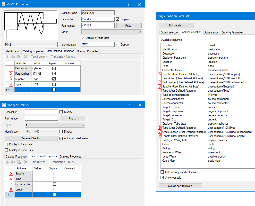
When adjusting the parts list, you must therefore ensure that you select the appropriate columns for listing. The same applies to the accumulated parts list. The template supplied contains columns related to the catalog attributes. If you replace these with the corresponding columns with your user-defined attributes, the accumulated parts list is filled correctly.
To top