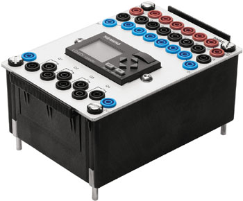
Logic module


The digital module is used for a compact embedding of a digital switching circuit into an electropneumatic or electrohydraulic circuit. The digital module offers 8 (16) electrical inputs and outputs, which transfer their states to its digital switching circuit in the inner part. Therefore the digital switching circuit does not need much space in the electropneumatic or electrohydraulic circuit for the display of the digital module as a rectangle with a total number of 18 (34) connections.
By making a double-click with the left mouse button on the digital module you come to the digital circuit in the inner part of the module. A new window opens. It shows the digital circuit and can be handled in the usual way. The standard configuration in the inner part of a new inserted digital module is a row with 8 (16) inputs and 8 (16) outputs each. They correspond to the inputs and outputs of the module in the electropneumatic or electrohydraulic circuit. In order to be able to test the digital circuit during the setup, it can be simulated separated from the electropneumatic or electrohydraulic circuit. As soon as the processing window of the digital module is closed or the original circuit window is put into the foreground, the previously effected changes in the digital circuit are automatically adopted into the digital module of the electropneumatic or electrohydraulic circuit.
Inside the digital module only digital components can be inserted. Furthermore, an encapsulating of additional digital modules inside a module is not possible. However, you can use several digital modules in one electropneumatic or electrohydraulic circuit. Please note that the digital circuit inside a digital module only works correctly if corresponding potentials are set at the electrical power supply units of the module (+24 V) and (0 V).