RS flip-flop
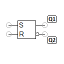
The RS flip-flop is an asynchronous flip-flop, which is controlled via the S (set) and R (reset) inputs. The flip-flop has two outputs Q1 and Q2, which are complementary to one another during normal flip-flop operation.
With S=1 and R=0, Q1 is set to 1 and Q2 is set to 0. With S=0 and R=1, Q1 is set to 0 and Q2 is set to 1.
The assignment of S=1 and R=1 is a special case, which should be avoided for the reasons outlined below. An RS flip-flop can be implemented in a number of ways using electronic components. The FluidSIM implementation corresponds to the real design consisting of two NOT and two NAND gates. Consequently, the assignment of S=1 and R=1 produces a stable state Q1=1 and Q2=1. Implementation with two NOR gates produces the stable state Q1=0 and Q2=0 for S=1 and R=1. In both cases, Q1 and Q2 are not complementary to one another.
A problem occurs with the transition from S=1 and R=1 to S=0 and R=0. This transition is, in any case, nondeterministic (virtually random), i.e. even the smallest runtime differences in the gates used decide whether (Q1=0, Q2=1) or (Q1=1, Q2=0) is achieved as the stable state. The same situation occurs when the supply voltage is applied.
The assignment of S=0 and R=0 has no effect on the current output values other than the problematic transition described above.
Adjustable parameters
| Designation | Range | Default value |
|---|---|---|
| Voltage level (lo) | 0.1 ... 24 V | 0.8 |
| Voltage level (hi) | 0.1 ... 24 V | 2 |
| Designation | Range | Default value |
|---|---|---|
| Voltage level (lo) | 0 ... 24 V | 0 |
| Voltage level (hi) | 0.1 ... 24 V | 5 |
| Resistance | 0.1 ... 1000 Ohm | 50 |