Schmitt trigger
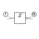
The Schmitt trigger (named after its inventor Otto Schmitt) converts an analogue input signal into a digital output signal. In the case of TTL modules, this means that any analogue input voltage between 0 V and 5 V at input I is transformed into a logic output level of either 0 V or 5 V at output Q.
This conversion takes place with the help of a lower and upper trigger level. If the input signal lies below the lower trigger level, the low level (usually 0 V) is output; above the upper trigger level the high level (e.g. 5 V) is output. The difference between the two threshold voltages is called hysteresis.
The output Q of the current Schmitt trigger is inverted, i.e. the low level is output if the upper trigger level is exceeded and the high level is output if the value falls below the lower trigger level.
If the input voltage changes only in the range between the lower and upper trigger level, the output level does not change.
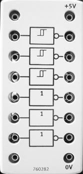
The IC 74HC14 is used as a component in the training package TP 1012 from Festo Didactic.
Adjustable parameters
| Designation | Range | Default value |
|---|---|---|
| Voltage level (lo) | 0.1 ... 24 V | 2.1 |
| Voltage level (hi) | 0.1 ... 24 V | 2.4 |
| Designation | Range | Default value |
|---|---|---|
| Voltage level (lo) | 0 ... 24 V | 0 |
| Voltage level (hi) | 0.1 ... 24 V | 5 |
| Resistance | 0.1 ... 1000 Ohm | 45 |