Limiter
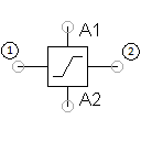
The limiter is a closed-loop control technology component. Within a defined voltage range, the input signal/potential at input 1 is replicated to another defined voltage range of the output signal/potential. In order to keep circuit wiring as straightforward as possible, required earthing (0 V) is not led out as a terminal, but rather wired internally.
The voltage range of the input and output signals are specified after selecting the Operating mode option. The output signal is additionally limited by the potentials applied to terminals A1 and A2 relative to ground (0 V). If a positive potential is connected to A1 and a negative potential to A2, the available output signal is no greater than the smaller numeric value of the two (example: A1 = +15 V, A2 = -10 V => control range = ±10 V). This can be further limited by means of a parameter, in order to take losses from the control electronics within the component into account.
The component does not generate an output signal unless a minimum potential is connected to both the A1 and the A2 terminals. The value can be adjusted in the advanced settings. If either terminal A1 or A2 is not connected to any potential, the potential of the connected terminal is passed through to the output (4).
This element is based on the element with the same designation from Festo Didactic’s equipment set for Basic principles of control technology
(TP 1013).
Adjustable parameters
| Designation | Range | Default value |
|---|---|---|
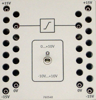
| Operating mode | In [-10 V..10 V] —> Out [0 V..10 V], In [-10 V..10 V] —> Out [-10 V..10 V], Enter manually | In [-10 V..10 V] —> Out [0 V..10 V] |
| Efficiency | 0 ... 1 | 0.9 |
| Min. Voltage (in) | -400 ... 400 V | -10 |
| Max. Voltage (in) | -400 ... 400 V | 10 |
| Min. Voltage (out) | -400 ... 400 V | -10 |
| Max. Voltage (out) | -400 ... 400 V | 10 |
| Minimum voltage | 0 ... 10 V | 1.5 |